V1.0 PCB MOD
Hi,
Follow this tutorial to upgrade your ZX Dandanator Mini 1.0 PCB to support eeprom updating from the Spectrum, either by sound (ear input) or by a Kempston interface and a USB-TTL Serial interface. WARNING: DO NOT USE RS232, the voltages are way different
There is a complete PCB building tutorial at this link
Hey! I amost forgot: DISCLAIMER: Do this mod at your own risk :).

MOD General description: What we are going to do

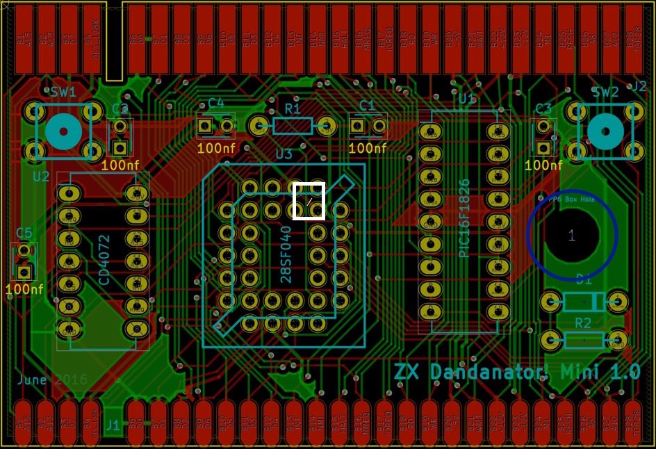
This mod isolates pin 31 (WE) of the PLCC eeprom memory, now connected to +5v, and connects it to the ROM WR OR output
(A14+A15+MREQ+WR). WARNING: This mod will only work with SST39SF040 eeproms.
We need to cut some tracks and connect some wires. Let’s focus first on trace cuts (and trace reconstruction)
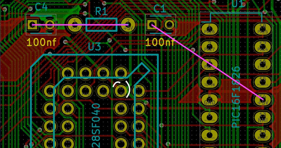
As you can see in the above picture, we need to cut 3 tracks (white lines around PLCC pin 31). Unfortunately, by cutting these tracks, we also cut the connection to other components in the PCB, so we need to reconstruct these connections by soldering two wires as shown with the magenta lines..
Note that the picture above is showing the component side. Most of the work will be done flipping the board to the solder side. Pay special attention to this to avoid doing the mod on pin 6 instead of pin 31!

OPTION 1: if your kit is already built

One of the tracks we need to cut, the red track on the upper left side on the above picture, is on the component side and it’s covered by the PLCC32 socket.
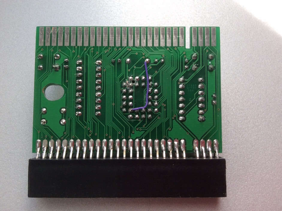
If you don’t have a desoldering station and/or the skills to desolder a PLCC32 socket, you can still cut that trace by drilling a small hole from the solder side. To do so, flip the board as shown in the picture below and locate pin 31, in the upper left internal corner of the PLCC32 socket in the picture below.
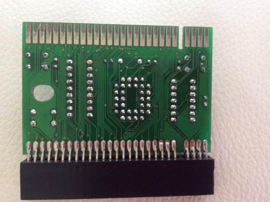
Using a tiny drill or a Dremel tool, drill a hole in between pins 31 and 32 of the PLCC32 socket from the solder side. Do not drill very deep. Just enough to get through the PCB. The right drilling point is shown in the picture below.
You also need to cut the tracks arriving at pin 31. I also use a Dremel tool for that. These cuts are also shown below.
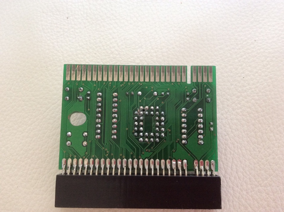
At this point we have successuly isolated pin 31 (Checking it with a tester is a good idea). By doing so, we have disconnected some other tracks as shown in the first picture of this tutorial and, also, by drilling the hole we have cut the vertical track on the solder side that passes between pins 31 and 32 of the PLCC.
Let’s start by reconstructing this trace with a wire as shown below.
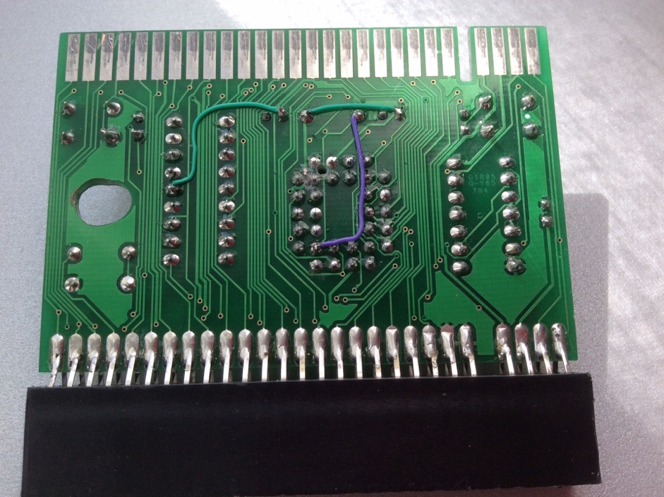
Now, let’s reconnect VCC to the points that were cut by isolating pin 31, as shown in magenta in the first picture of the tutorial.
This is done by soldering two wires (green in the next picture)
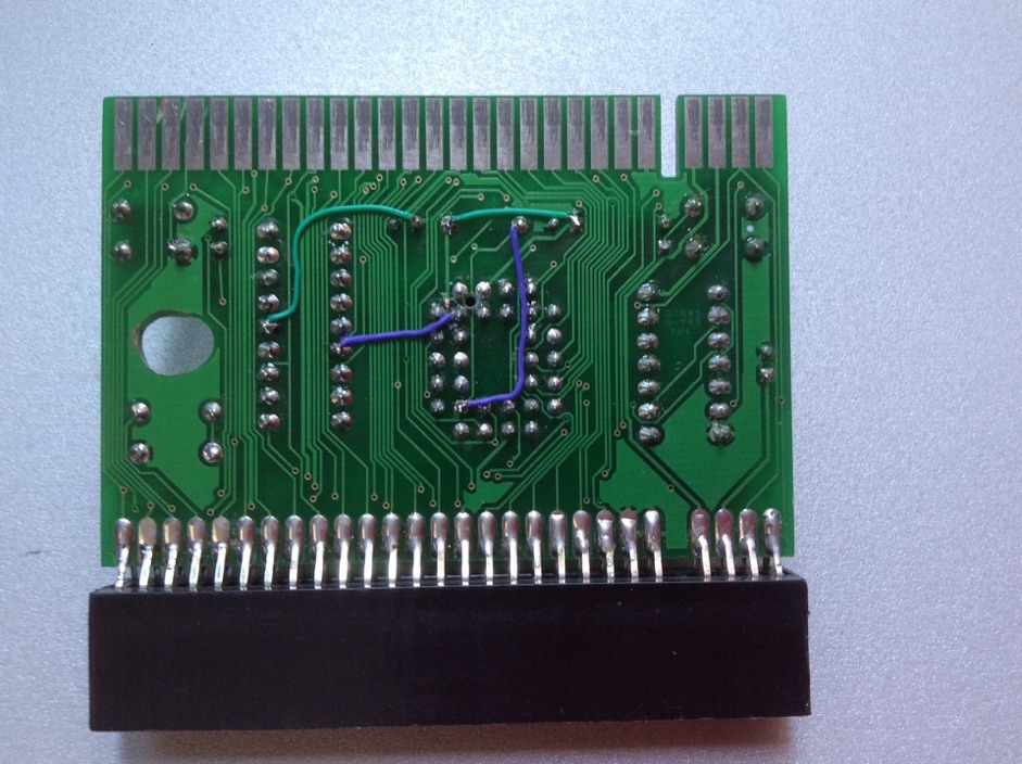
Last step is connecting the PLCC32 Pin 31 (Write Enable) to the Rom Write signal from spectrum. This is either pin 13 of the CD4072 gate or PIN 6 of the PIC microcontroller. The following picture shows this connection to the PIC.
That’s all. You can now use the 6.0 software feature to update the eeprom contents from the spectrum, either by audio or by kempston serial.
Please, do notice that you need to update your eeprom or your PIC at least once using external methods (programmer).

OPTION 2: If your kit is not assembled yet

If you haven’t built your kit yet, the process is quite similar to the one described above. Instead of drilling the hole and reconstructing the destroyed trace (with the Inverted L-shape purple wire in the pictures above), you need to cut the track on the component side before soldering in the PLCC32 socket.
Ths cut point is shown in the diagram below, the small cut over the red track.
For the remaining part, just follow the steps above (Option 1).