
HW Schematics

Hardware-wise, the board is quite simple and it only uses three ICs and some passive components. I used KiCad 4.0.2 for Mac for designing the PCB. Thanks Kyp for edge connector footprint!. Routing was done with the free tool FREEROUTER
KiCad and Gerber files are available at the Downloads page .
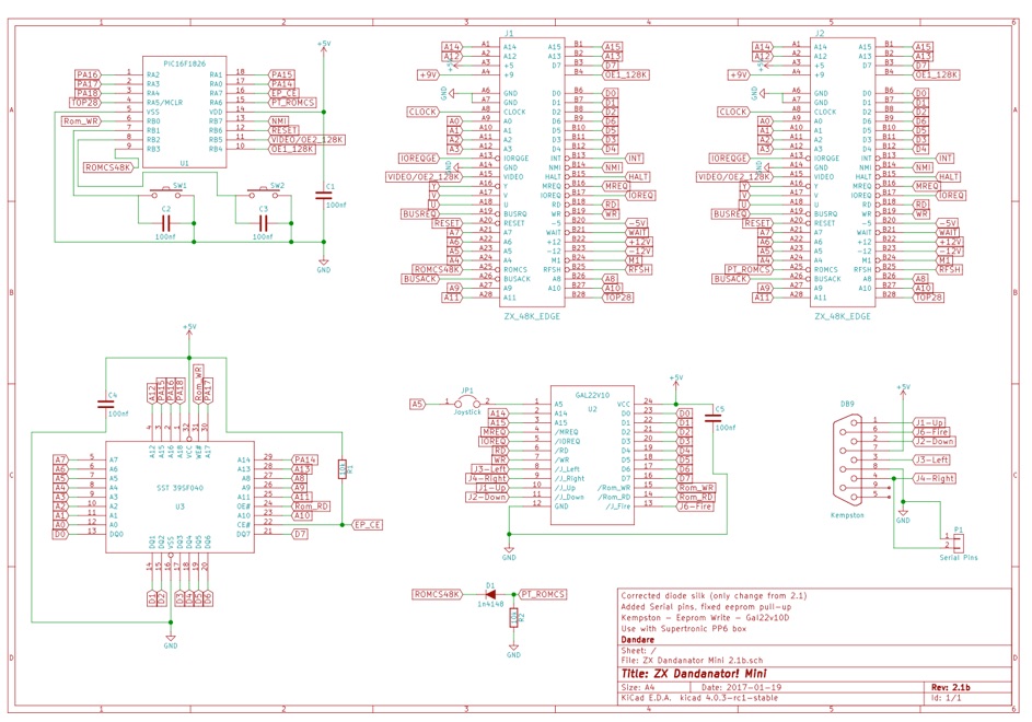
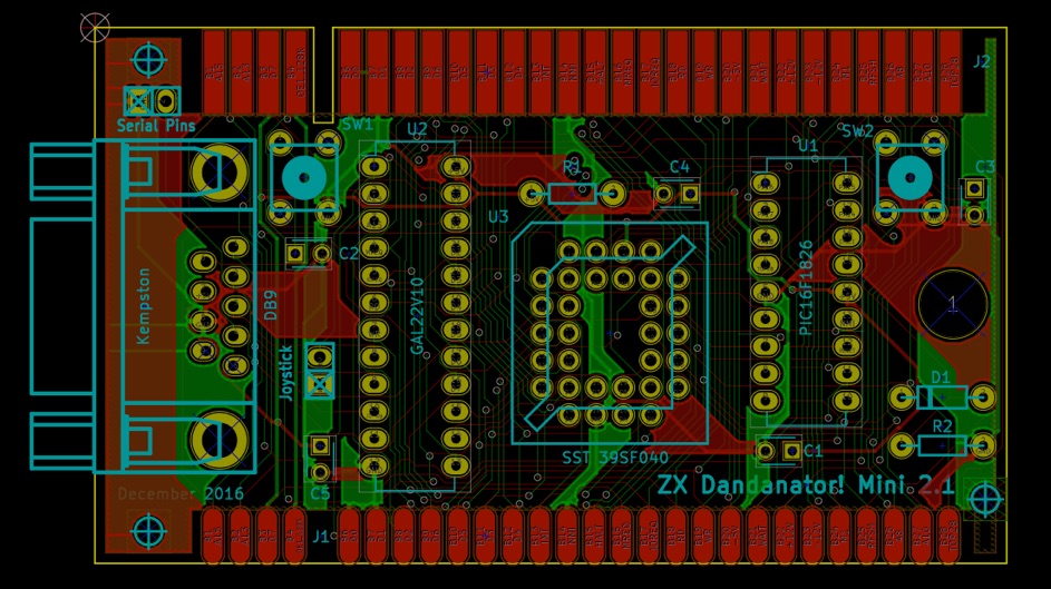
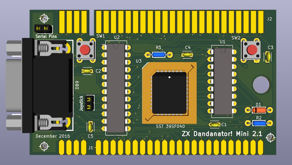
These are the 2.1b (latest) schematics and PCB images

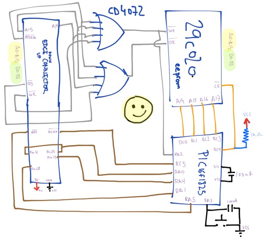
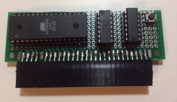
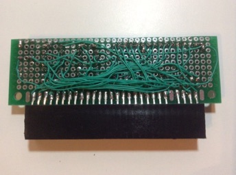
The first prototype (that was the basis for v1 boards) was made using a DIP 2Mbit (256kb) memory chip and a smaller footprint microcontroller, a PIC16F1825 instead of the current PIC16F1826.
Design software used was somewhat different as well :D...

PIC microcontroller is in charge of button actions, RomcS/OE activation, rom page selection and non-volatile memory storage&retrieval. It also identifies the type of Spectrum it’s connected to and configures itself accordingly.
Only means of communication between the Z80 and thePIC is by writing on the ROM space. Since some commercial programs, and even the Spectrum Rom itself, try to write to rom sometimes, the microcontroller is aware of what is running and decides whether to pay attention to the commands received or not. There is a full command list for configuring the board from the Spectrum, such as selecting boot options, button behavior or non-volatile RAM management.
Spectrum-type detection by the PIC microcontroller is done by a method I haven’t seen in any other place, so unless there is some prior art about it, I claim its invention ;).
This detection is needed to activate either /ROMCS or /OE1 /OE2 signals on a 16/48/128k and +2/+3 respectively everytime the board needs to take control of the ROM space. Typical method of doing so is by means of a jumper, but this board does it automatically.
The PIC monitors pin B28 (Top28) of the edge connector, on 1-rom chips spectrums, this pin is unconnected and floating. On 2-rom chips models, this pin carries a delayed (around 90ms) inverted signal of /Reset.
By connecting this B28 to an input pin of the microcontroller and enabilng a Pull-up, while monitoring the /Reset signal, we can decide whether the computer is, effectively, a 1-rom IC spectrum or a 2-rom IC spectrum. This way, the PIC knows what signals to activate to disable the internal Spectrum ROM.
This technique has been tested on most Spectrums and harlequins (no toastrack because I don’t have one) and should work on TK90/95 clones as well. I haven’t tested it on Inves Spectrums, so please contact me if you have one so we can figure it out.
The PIC microcontroller also monitors /ROMCS requests upstream (done by other peripherals connected after it) and disables itself if it detects any. This allows, for instance, to stack several dandanators mini in the same spectrum (mind the poor 7805 regulator!)
